Andy MacDonald | May 20, 2024 | 8 min read
Product Verification Control Box Helping keep old machines profitable.
A manufacturer of hydraulic products recently contacted VoxSomnia to develop a low-cost, custom device to remedy a problem in their end of line testing process. Product order sheets could be mistakenly switched with different products, and the products were close enough in specification and appearance that an incorrect product could be qualified on the test machine and shipped to their end customers by mistake, generating costly rework and harming customer relations.
The machine is several decades old with many obsolete components that cannot be modified. An overhaul of the machine was out of budget. Instead, the customer needed a cost-effective way to enhance the machine so that only valid products could be tested.
The team worked with the customer’s manufacturing engineer to develop a plan. The device had the following major requirements identified upfront:
- Costs kept to a minimum
- Indicate to the operator if parts matched
- Function independently of machine test software (legacy and inaccessible)
- Have memory to store product numbers
- Able to send 24V input and output signals to test machine components
- Not require a PC & monitor
- Scan item numbers with a handheld scanner from order sheets and product labels
- Resist oily environments
- Allow for the customer to update product numbers independently
Hardware:
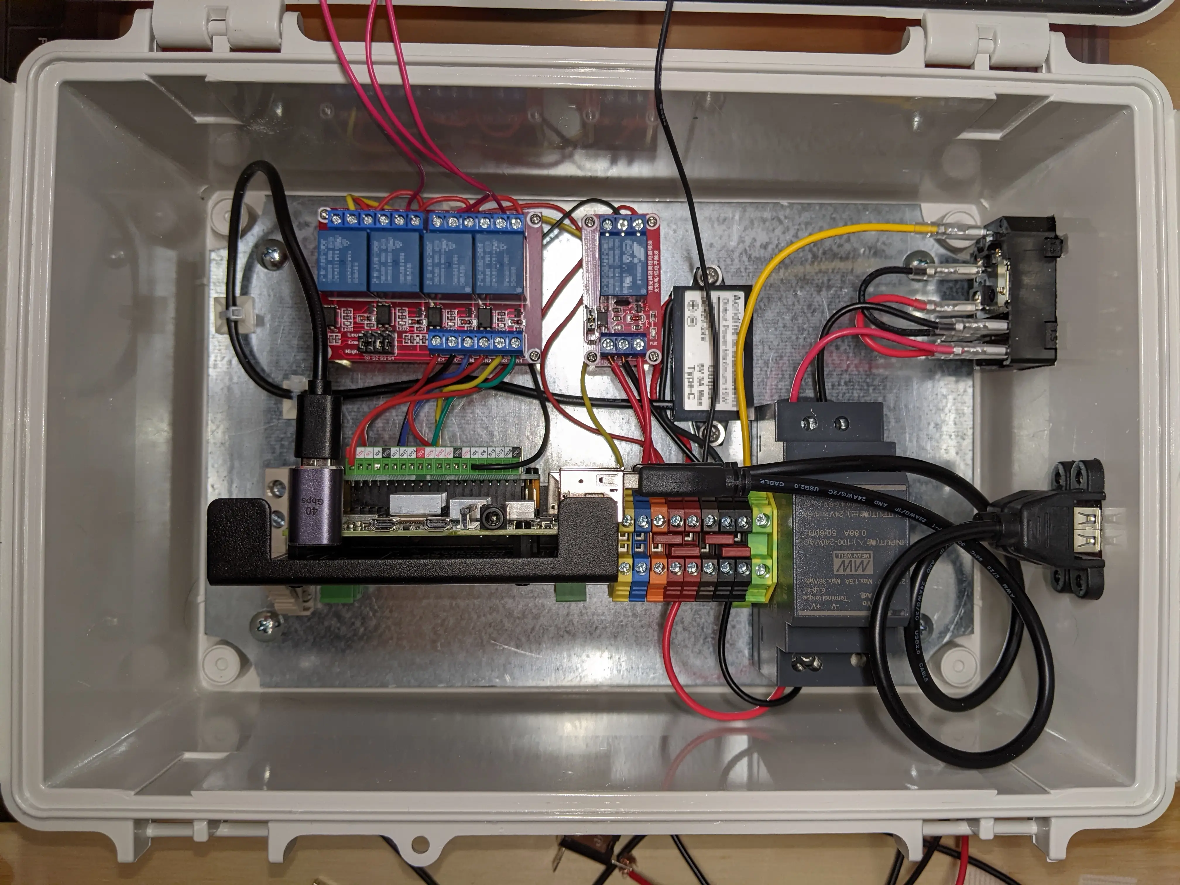
Industrial PLC’s and NI hardware were avoided to meet tight cost requirements. A general-purpose input/output (GPIO) was necessary. A Raspberry Pi was chosen. It is low cost, has general input/output function, is programmable, embedded, and has onboard USB inputs to connect to other hardware.
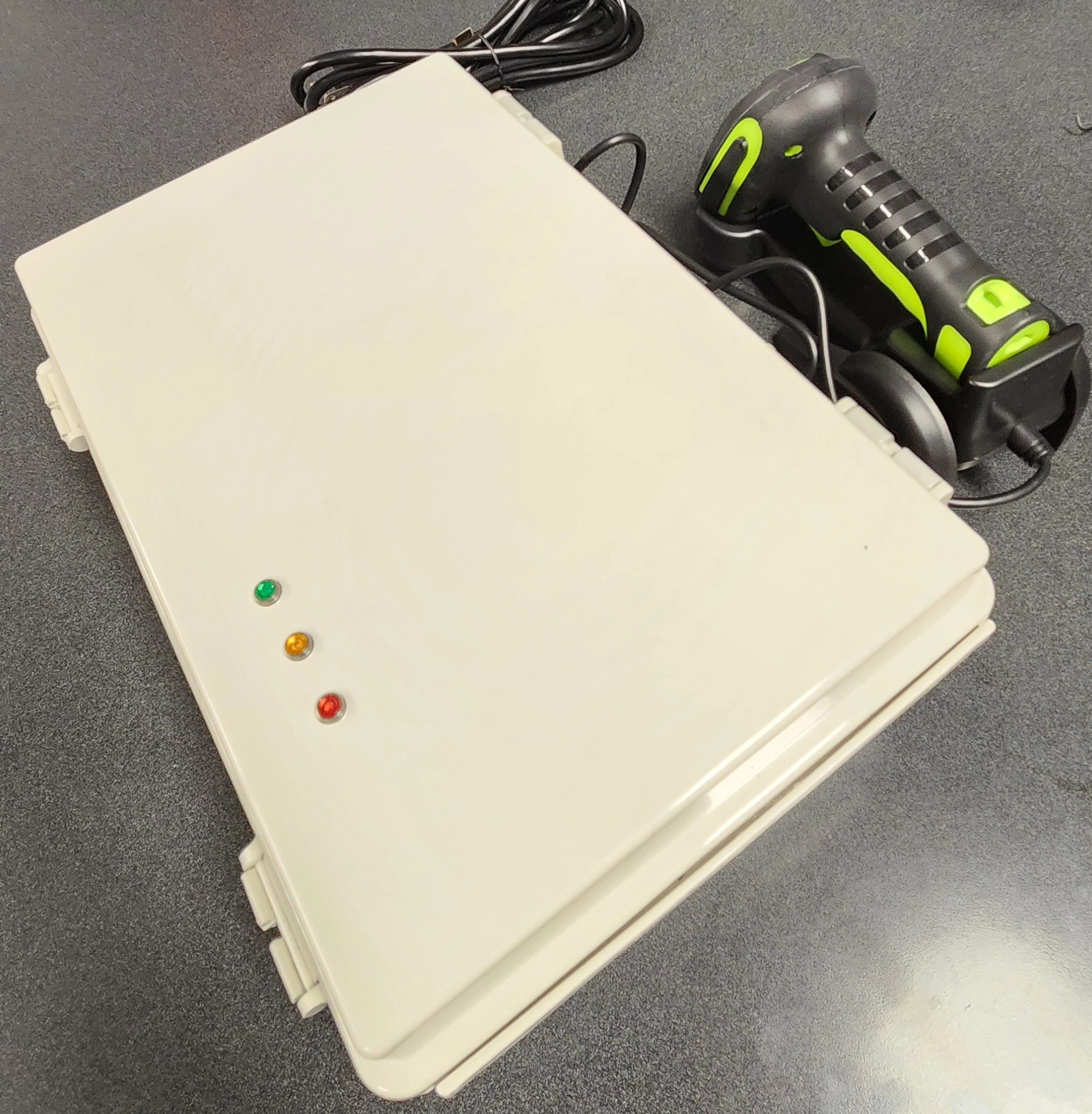
Communication with the operator needed to avoid an expensive HMI (human-machine-interface). A stack light and LEDs were chosen to communicate device states to the operator.
Raspberry Pi’s have very limited input and output signal strength. The 24V requirement would need to be achieved by stepping up signals from a dedicated power supply using relays. The relay allows the low-voltage Raspberry Pi signal to be translated to a higher 24V signal which can drive most industrial components.
To allow the customer to upload new product information, the onboard USB port would be used.
The part numbers on order sheets and product labels would be scanned into the system with a hand scanner plugged into the second USB port.
Finally, the enclosure box was selected per IP66 and NEMA 4 to protect electronics from the oily factory.
Software:
VoxSomnia strives to use the tool best fit for any given solution. With the relatively small number of functions on this project, and minimal simultaneous operations, Python was chosen as the language to control the device.
The customer kept product information in a Microsoft Excel spreadsheet, and so this was chosen to be kept as the source of data uploaded to Python.
Solution:
With requirements captured as far as they could be, and hardware & software defined, the team got to work designing and programming the Product Verification Box (or “Scanner Box” for short).
At project outset, it is common to have a rough idea of the what the final implementation will look like, but it is rare and difficult to capture all requirements upfront. The team began planning through the different functions:
- Make it clear to an operator that the device is ready to scan, and that a scan was accepted or rejected
- Prevent operators from circumnavigating the device
- Accept a new CSV file (customer preferred Excel) with updated product list
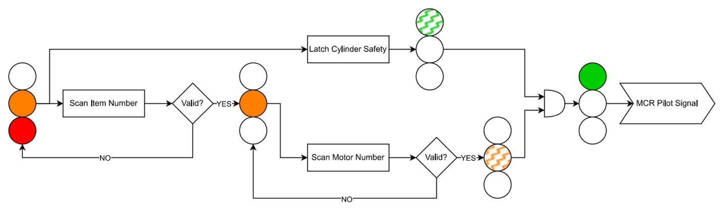
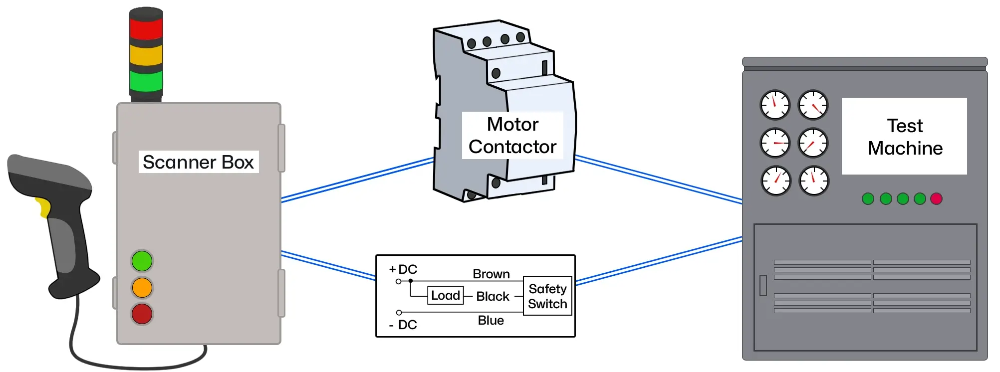
Prior to scanning, the Scanner Box keeps the test machine disabled, so that operators cannot test parts by mistake. Once the operator scans a product sheet, subsequent scans of labels must match the product sheet. If the labels match, the device triggers the contactor (a high-current electrical switch) to enable the machine to test one product.
Partway through the project, there was the addition of a safety requirement for the operator. The product, or device under test (DUT), could be improperly loaded into the machine which could result in operator injury. This project created a good opportunity to ensure the product was properly loaded before a test could commence. To accomplish this, an inductive switch was added to the physical test fixture that triggers an ON signal back to the scanner box only when the DUT is properly installed. This safety feedback signal to the box (and relevant coding) was added to the requirements.
Once a DUT is tested, the machine sends the OFF safety switch signal back to the Scanner Box to let it know it was removed from the machine. The Scanner Box then disables the test machine until another matching label is scanned, repeating the process.
Hardware Build & Test:
The box was assembled and thoroughly tested per the requirements, with close communication with the customer. Several snags were run into when testing. There were signal timing issues with the initial prototype build that caused the device to sometimes get “stuck” in an off state. There were also voltage triggering problems that would prevent the system from turning off. The team worked feverishly to test all possible conditions and operator input sequences, slowly working out timing, triggering, and electrical issues.
Once the Scanner Box passed tests for all requirements, it was delivered to the customer for final implementation. A stack light was added to the box to make the machine state obvious to the operator and anyone nearby, and the additional terminals for the contactor and safety switch were wired by the customer.
With this project completed, the customer now has a more profitable machine asset that did not require a costly major overhaul!
About the author
